Click Reset ()
Power/Reset click has two PCB pads, used to sense touch or proximity events. These pads are the only elements on the superlative of the lath, allowing installation of the protective acrylic glass layer. These pads are marked as ON/OFF and RESET in order to offer to a user a simple solution for a capacitive switching power and reset controls for various devices. This click lath™ includes all hardware and signal processing functions necessary to provide stable sensing under a broad multifariousness of changing conditions.
How does information technology work?
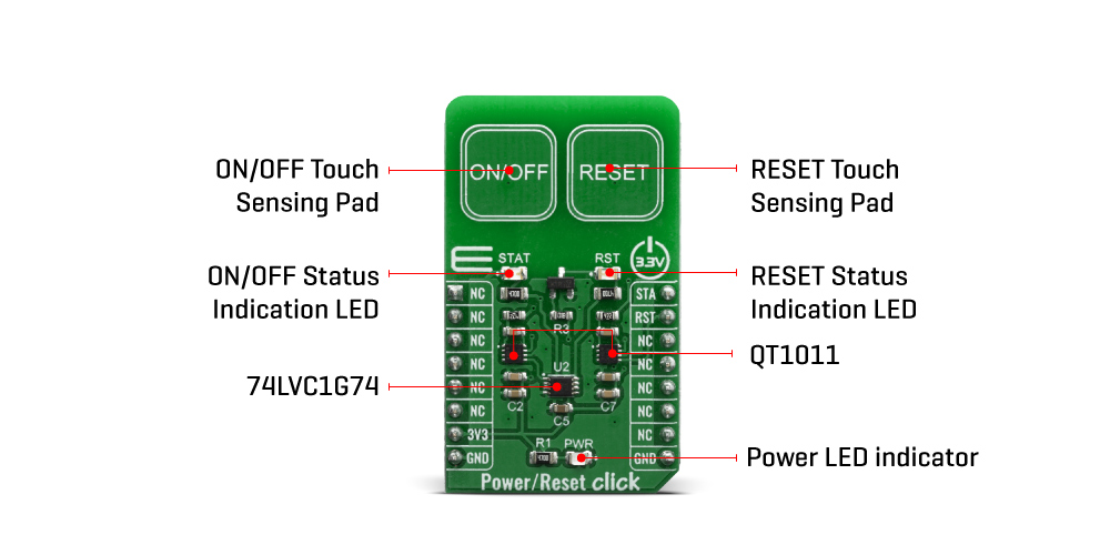
Power/Reset Click is a capacitive touch sensing Click board™ which features the QT1011, digital burst mode accuse-transfer sensor that is capable of detecting nigh proximity or bear on, from Microchip. This click board™ has two PCB pads, used to sense touch or proximity events. Besides the two touch sensitive pads, Power/Reset click has ii LED diodes for the touch indication. The 2 bear on pads use ii divide QT1011 ICs, providing a very reliable touch sensing functionality.
The AT42QT1011 is a digital outburst mode accuse-transfer sensor that is capable of detecting nearproximity or impact, making information technology ideal for implementing touch controls. With the proper electrode and excursion blueprint, the self-contained digital IC will project a touch or proximity field to several centimeters through any dielectric like glass, plastic, rock, ceramic, and fifty-fifty nigh kinds of wood. It can also turn small metal-bearing objects into intrinsic sensors, making them responsive to proximity or touch. This capability, coupled with its ability to self-calibrate, tin can atomic number 82 to entirely new product concepts.
The QT1011 is designed specifically for homo interfaces like control panels, appliances, toys, lighting controls, or anywhere a mechanical switch or button may exist found. It includes all hardware and signal processing functions necessary to provide stable sensing under a wide variety of changing conditions. All the same, this click board™ is designed to serve as a ability and reset capacitive switch panel lath.
Likewise the QT1011, this click board™ contains 74LVC1G74 besides. Information technology is a Unmarried D-type flip-flop with prepare and reset. Because The output of the QT1011 is active-high upon detection, the 74LVC1G74 is triggered by the positive edge of the ON/OFF touch pad. Information technology is wired in a cascade with the QT1011 in fashion that ensures holding 1 logical state until the ON/OFF pad is pressed. Therefore, the ON/OFF pad acts similar a switch, while the RESET pad acts similar a push, which is suitable for most common purposes.
The output signals for the ON/OFF and RESET pads are wired to the PWM and INT pins on the mikroBUS™, respectively. Also that, the STAT and RST LEDs are wired parallel to the outputs in lodge to ensure a visible indication of the status of the pins.
This Click Board™ is designed to be operated only with 3.3V logic level. A proper logic voltage level conversion should be performed before the Click lath™ is used with MCUs with logic levels of 5V.
Specifications
| Type | Capacitive |
| Applications | Bear on activated lighting controls, touch activated command panels, toys and any other applications that demand a switch or a push button for powering and resetting a device. |
| On-board modules | QT1011, digital outburst manner charge-transfer sensor that is capable of detecting near proximity or impact, from Microchip. |
| Key Features | Reliable capacitive touch detection technology, noise filtering, Patented spread-spectrum charge-transfer (direct mode), Increased moisture tolerance |
| Interface | GPIO |
| Compatibility | mikroBUS |
| Click board size | K (42.9 ten 25.four mm) |
| Input Voltage | 3.3V |
Pinout diagram
This table shows how the pinout on Power/Reset Click corresponds to the pinout on the mikroBUS™ socket (the latter shown in the two center columns).
| Notes | Pin | | Pin | Notes | |||
|---|---|---|---|---|---|---|---|
| NC | 1 | AN | PWM | 16 | STA | ON/OFF Status Out | |
| NC | two | RST | INT | 15 | RST | Reset Out | |
| NC | 3 | CS | RX | 14 | NC | ||
| NC | four | SCK | TX | 13 | NC | ||
| NC | 5 | MISO | SCL | 12 | NC | ||
| NC | 6 | MOSI | SDA | 11 | NC | ||
| Power Supply | three.3V | 7 | 3.3V | 5V | ten | NC | |
| Basis | GND | eight | GND | GND | 9 | GND | Ground |
Onboard settings and indicators
| Label | Name | Default | Clarification |
|---|---|---|---|
| LD1 | STAT | - | ON/OFF Status Out |
| LD2 | PWR | - | Ability LED Indicator |
| LD3 | RST | - | RESET Status |
Software Support
We provide a library for the Power/Reset click on our LibStock page, equally well as a demo awarding (example), developed using MikroElektronika compilers. The demo can run on all the main MikroElektronika evolution boards.
Library Clarification
This library allows user to check which push is pressed or activated. Also initializes GPIO driver. For more than details check documentation.
Key functions:
-
void touchbutt_gpioDriverInit(T_TOUCHBUTT_P gpioObj)- This function initializes GPIO driver. -
T_TOUCHBUTT_STATE touchbutt_getPWR( void )- This office returns a state of the PWR pin (ON/OFF button). -
T_TOUCHBUTT_STATE touchbutt_getRST( void )- This function returns a land of the RST pin (RESET button).
Examples description
The application is equanimous of iii sections :
- System Initialization - Initializes peripherals and pins.
- Application Initialization - Initializes GPIO driver and performs a timer interrupt configuration.
- Application Task - (code snippet) - Checks the states of the PWR and RST pins and performs a control of the timer counter depending on the pressed button (pins state). User tin start and stop a timer counter, in the resolution of 100ms, by pressing the ON/OFF button. As well tin can reset a timer counter to 0 past pressing the RESET push. When timer counter was reached the target time (in seconds), a message will be sent to the uart terminal and the sound will be generated. Timer counter state will be showed to the uart terminal.
void applicationTask() { pwr_state = touchbutt_getPWR(); rst_state = touchbutt_getRST(); if ((pwr_state == _TOUCHBUTT_ACTIVE) && (time_cnt_prev != time_cnt) && (rst_state == _TOUCHBUTT_INACTIVE)) { time_val_dec = time_cnt / 10; time_val_real = time_cnt % 10; LongWordToStr( time_val_dec, text ); Ltrim( text ); mikrobus_logWrite( text, _LOG_TEXT ); mikrobus_logWrite( ".", _LOG_TEXT ); ByteToStr( time_val_real, text ); Ltrim( text ); mikrobus_logWrite( text, _LOG_LINE ); if ((time_val_dec >= target_time) && (alarm_flag == _TOUCHBUTT_ACTIVE)) { mikrobus_logWrite( "** Target time is reached! **", _LOG_LINE ); alarm_flag = _TOUCHBUTT_INACTIVE; Sound_Play( 1000, l ); Delay_ms( 40 ); Sound_Play( 1000, 50 ); Delay_ms( 40 ); } } if (rst_state == _TOUCHBUTT_ACTIVE) { time_cnt = 0; alarm_flag = _TOUCHBUTT_ACTIVE; } else { time_cnt_prev = time_cnt; } } The total application code, and set to use projects tin can exist found on our LibStock page.
Other mikroE Libraries used in the case:
- Conversions
- C_String
- Sound
- UART
Additional notes and informations
Depending on the development board yous are using, yous may need USB UART click, USB UART 2 click or RS232 click to connect to your PC, for development systems with no UART to USB interface available on the board. The terminal available in all MikroElektronika compilers, or any other terminal awarding of your choice, can be used to read the message.
mikroSDK
This Click board™ is supported with mikroSDK - MikroElektronika Software Development Kit. To ensure proper performance of mikroSDK compliant Click board™ demo applications, mikroSDK should be downloaded from the LibStock and installed for the compiler you are using.
For more data about mikroSDK, visit the official folio.
Resources
Downloads
Source: https://www.mikroe.com/power-reset-click
0 Response to "Click Reset ()"
Post a Comment